Difference between revisions of "StackClock"
From Hackstrich
| Line 2: | Line 2: | ||
== Status == | == Status == | ||
| − | * 2017-12-16: | + | * 2017-12-16: Assembled the first Display board, haven't had time to program/test it beyond initial power-on, draws ~10mA and nothing gets hot when power is applied. |
* 2017-12-01: Display boards have arrived, ordered all parts except IR receiver and AS1115 chip which are backordered (the latter until March!). | * 2017-12-01: Display boards have arrived, ordered all parts except IR receiver and AS1115 chip which are backordered (the latter until March!). | ||
* 2017-11-20: Did final review of Base board, sent off to OSH Park for manufacturing. | * 2017-11-20: Did final review of Base board, sent off to OSH Park for manufacturing. | ||
Revision as of 20:01, 16 December 2017
I'd like a series of clocks on my desk at work to show various timezones. The hardware and firmware files are on github at sarahemm/stackclock.
Contents
Status
- 2017-12-16: Assembled the first Display board, haven't had time to program/test it beyond initial power-on, draws ~10mA and nothing gets hot when power is applied.
- 2017-12-01: Display boards have arrived, ordered all parts except IR receiver and AS1115 chip which are backordered (the latter until March!).
- 2017-11-20: Did final review of Base board, sent off to OSH Park for manufacturing.
- 2017-11-01: Did final review and fixed a couple issues on the Display board, sent off to OSH Park for manufacturing.
- 2017-10-30: Completed the Base board and checklisted it.
- 2017-10-22: Completed and checklisted the board layout for the Display board. 24h waiting period now, then will send off to be manufactured. Now that Display layout is complete, can finish the Base board.
- 2017-10-21: Completed and checklisted the schematic/BOM for the Display board.
- 2017-10-17: Started putting together BOM/schematic for Display board.
- 2017-10-17: Did as much routing of Base board as possible without knowing how big the Display boards will need to be.
- 2017-10-10: Completed and checklisted Base schematic, started routing board.
- 2017-10-04: Put together most of the schematic for the Base Board, just need to finish the USB interface, IR emitter, and diagnostics (test points, etc.).
- 2017-09-17: Started working on this again, putting BOM together and such.
- 2016-09-15: Started putting this idea together.
- 2015: Tried to find some commercial clocks I could stack up to make this, failed to find anything nice looking that supported 24h time. The Hayes Stack Chronograph would be cool but they're very rare now.
Specs
- Arduino-compatible Base Board on the bottom has the RTC and keeps time
- Supports multiple oscillator options:
- TCXO (cheap, stable to ~216ms/day)
- OCXO (less cheap, stable to ~840us/day or 305ms/year)
- External 10Mhz clock input from a Rb/Cs or other reference
- Has an encoder on it to allow changing the time briefly to compare between time zones
- For instance, "this log is in UTC and it says 0502, what time was that in Calgary?"
- A few seconds after the encoder stops rotating, display goes back to real time
- Supports multiple oscillator options:
- Arduino-compatible Display Boards stack on top of that board
- As many as you want to stack (up to maybe 8 or 16, but the bus limit with the current design would be 127)
- Each display board has:
- 3 alphanumeric LED displays to show which timezone
- 4 numeric LED displays to show the time (or maybe 6, need to decide if they'll include seconds)
- Using displays available in Red, Yellow, and Green so can have different "levels" of the stack different colours
- Stack communicates internally via I2C
- SCL/SDA and power carried on standoffs
- Stack is configurable via USB interface
- Also initial time set will happen via USB from an NTP server, once set it can free-run for a long period while staying accurate
Enumeration Process
I want the display boards to figure out what order they're in without needing to set any DIP switches or anything. To accomplish this, each board has an IR emitter pointing up, and an IR detector pointing down.
Calibration Phase
- Base sets ENUM as output and lowers it, displays set ENUM as input.
- All boards toggle emitter on and off while recording min/max detector levels.
- After CALIBRATE_TIME, base raises ENUM to start the enumeration process.
Enumeration Phase
- All boards set ENUM_COUNT as an input and reset an internal counter to zero.
- Base turns on LED, waits for ENUM_COUNT to go high.
- Whichever board sees their detector goes high:
- Sets themself as node #1.
- Sets ENUM_COUNT as an output briefly.
- Raises ENUM_COUNT for COUNT_HOLD_TIME.
- Sets ENUM_COUNT back to an input.
- Any boards that didn't see their detector go high just increment their counter and continue on.
- Once ENUM_COUNT is low again, the board that was enumerated in step 3 turns its LED on, repeats steps 2-4.
- When a board turns its emitter on and ENUM_COUNT does not go high in ENUM_TIMEOUT time, the enumeration process is complete.
Standard Dimensions
SCL standoff is considered 0,0 for all of this, + is up/right, - is down/left.
| Item | X | Y |
|---|---|---|
| SCL Standoff | 0 | 0 |
| SDA Standoff | 0 | +0.4 |
| GND Standoff | +4.75 | 0 |
| VIN Standoff | +4.75 | +0.5 |
| IR TX/RX | +2.75 | +0.025 |
| Lower Left of Board | -0.6750 | -0.25 |
Display Rev001 Issues
- CN1/CN2 are 2 pins longer on BOM than they are on board.
- CN2's pins on the display side need to be realigned slightly to not interfere with the displays.
- DSP4-7 are physically missing the NC pins, should check the datasheet and eliminate these holes from the board if it guarantees this will always be the case, to make assembly easier.
- All display pins should have more exposed metal to make them easier to solder.
- Spacing is bigger between DSP2-DSP3 than between DSP1-DSP2
Gallery
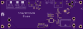
Base board Rev001, top
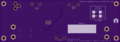
Base board Rev001, bottom
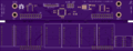
Display board Rev001, top
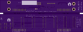
Display board Rev001, bottom